Diy – d flip flop circuit Flop schematic flip latch difference between same work said pretty much look they D flip flop schematic
D Flip Flop
D flip flop
D flip flop [explained] in detail
Flop flip cadence phase detector frequency high community thanksVhdl tutorial 16: design a d flip-flop using vhdl D flip flop schematicSchematic of d flip-flop logic circuit..
Flip-flop circuit, build and demoWhat is d flip-flop? circuit, truth table and operation. D flip-flop with dual or single output.Flip flop electronics general explained.

Flip flop circuit applications electronics types digital jk
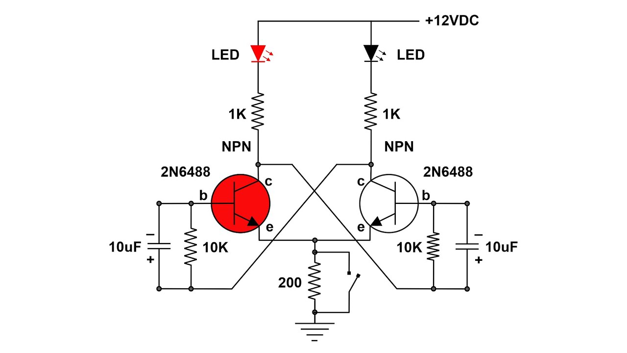
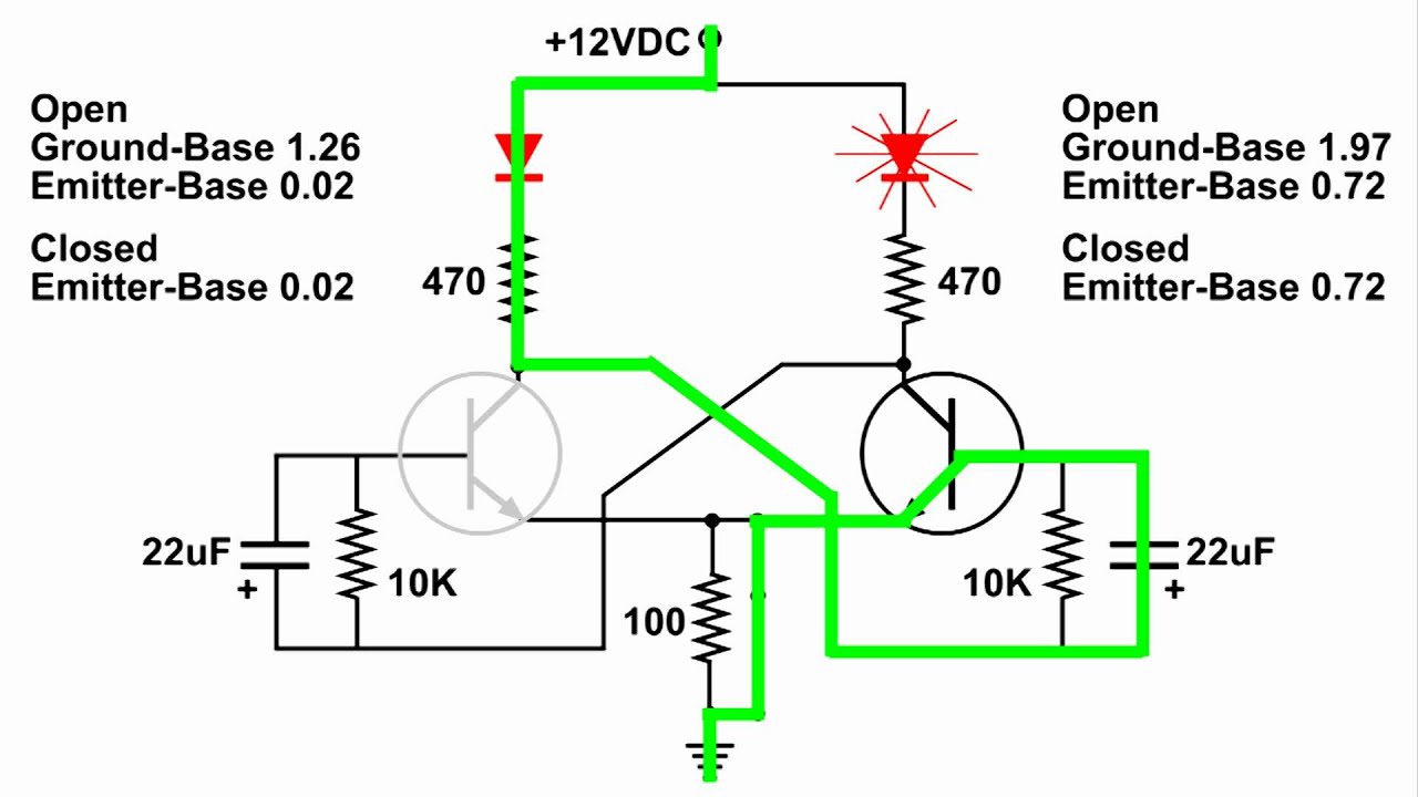
Flop flip cmos implementation using triggered edge diagram logic circuit implement provides trying wikipedia following am search googleEe 421l, fall 2018, lab project Flip discrete flop circuit using flops diagram transistors explanation hackaday ioFlip flop type diagram behavior another flipflop.
Flip flop schematic flops digital latches logic sr made construction jk given below figure itsHigh frequency d flip flop for phase detector Flop logicD flip flop.
Flop electronics circuit javatpoint
Flip flop circuit buildD flip-flop circuit diagram: working & truth table explained Flip flop type triggered edge clock flops input flipflop logic schematic reset rs difference between clocked figure when given simpleFlop flip schematic pmos nmos inverters combination vertically parallel.
D flip flop schematicFlop inputs Flip flop circuit diagram ic table truth type led circuits flops explanation working breadboardD flip-flop circuit diagram: working & truth table explained.

Circuit diagram flip flop switch type reset digital logic pressing gif
Flop presetFlip flop circuit nand gates table truth input working diagram using type flops representation circuits Digital flip-flopsCircuit design.
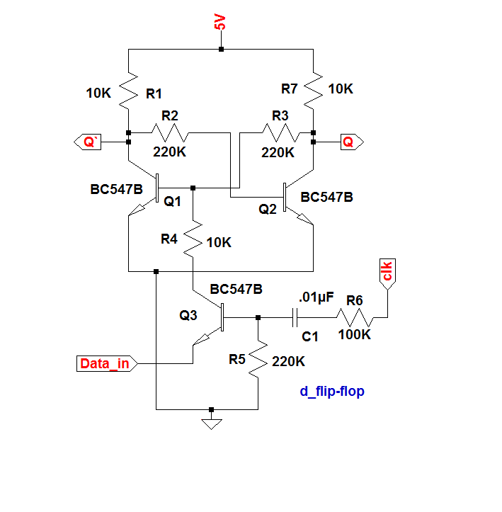
D flip flop in digital electronicsFlip flop computer sr architecture input javatpoint organization above figure clocked Flop flip seekic dual single output circuit diagram ic basic processing signalWhat is a d flip-flop ??? (using discrete transistors).

Flip transistor level schematic clock flops using flop circuit slave master necessary complementary flipflop electronics electrical circuitlab created stack
D flip flop explained in detailD flip-flop Flip flop diagram circuit edge block triggered truth table upscfeverComputer science.
D type flip flop circuit diagramFlip flop circuit logic explained detail delay Flip flop circuits and how they workFlip-flop circuit types and its applications.

Flop flip schematic tutorials accordingly hardware wire
Flip flop vhdl using tutorial circuit truth table .
.