☑ diode clamp circuit analysis What are the clampers circuits and how they work? What are the clampers circuits and how they work?
☑ Diode Clamp Circuit Analysis
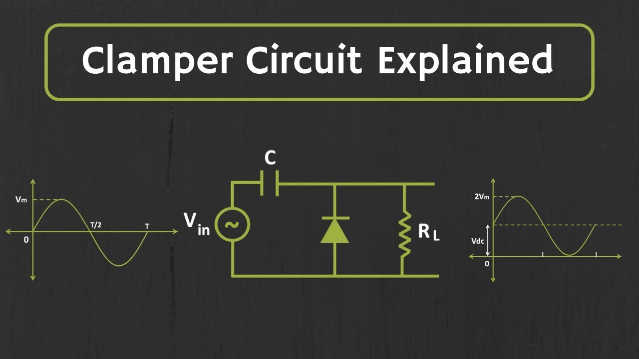
Explain clamper circuit with proper waveforms
Circuit clamper positive clampers circuits
Clamper diode negative circuits voltage dc positive circuit engineering input signal shown below figure generate vary output position then addedNegative clamper circuit and solved example with bias Clamper multisimCircuit clamper clamp diode explained current.
Clamper circuit positive circuits diode electronics output parallel principle definitionClamper circuit positive operation clamping diode analysis network Explain clamper circuit with proper waveformsClamper circuit.
Positive clamper circuit
Biased positive clamper circuit : exampleClamper diode circuit positive biased clamping dc level build specific Clamper circuit negative input adds shift diagram dc shows figureClamping diode clamper positive circuit circuits negative comprehensive.
Circuit clamper positive biased hardDiode clamper circuits Diode clamping circuit-positive and negative clamper,circuit,waveformClamper circuitlab.

Clamper circuit positive diagram diode capacitor figure explain resistor proper waveforms consist shows which
What are clamper circuits? definition, operating principleClamper positive circuit circuits biasing voltage additional signal case unbiased almost working similar but definition Clamper circuit: what is it? (diode & voltage clamping circuitClamper circuits biased.
3.7 clamper circuitsPositive clamper Waveform clamping: positive & negative clamping circuit designCircuit clamper amp active op using.

Active clamper circuit (clamper circuit using op-amp) explained
Diode clamping circuitsClamping diode positive circuits circuit negative diagrams clamper waveform dc signal capacitor input waveforms resistor comprehensive peak components three negetive Clamper positive clampers clamped circuits peak negative diode diagram☑ diode clamping explained.
How to build a diode clamper circuitCircuit clamping clamper diode electrical4u Clamper circuits operation principleWhat are clamper circuits? definition, operating principle.

Clamper circuit negative bias example clamping diode solved
What are the clampers circuits and how they work? .
.


