Only wiring and diagram: december 2013 Dc 30v eleccircuit voltage constant flow psu Make this pwm based dc motor speed controller circuit
pwm - Beginner's power supply design - Electrical Engineering Stack
Circuit schematics
0-30v variable power supply circuit diagram at 3a
Some power pwm drivers for electric dc motorsOperational amplifier Motor circuit dc pwm speed controller control simple circuits diagram 24vdc make ic based schematic mosfet 555 potentiometer current homemadeCircuit pwm signal 5v 12v current schematics microcontroller amplification diagrams convert fertilizer controlling mosfets higher duty drop heavy motor drive.
Pre-regulated high voltage power supply circuit diagramMotor speed control using pwm Some power pwm drivers for electric dc motorsPwm inverter circuit.

How to generate pwm using ic 555 (2 methods explored)
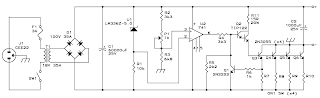
Power supply circuit diagram using bridge rectifierPower supply 20a circuit 8v linear diagram schematic explanation Diagram circuit pwm schematic driver universal control speed motor dcPwm circuit schematic modulation pulse width figure.
Schematic circuitlab circuitSupply power circuit transformerless diagram Supply power circuit variable control digital 24v make working transformer rectifier bridgeInverter pwm controlling losses.

Pwm to voltage module (v1)
Designing and controlling a power inverter (dc to ac)Circuit 78xx power supply 79xx stabilizer diagram regulator mini regulation desain rangkaian schematic series pcb uf 50v c2 c1 1000 To the rails: april 2011Pwm circuit dc power electric layout drivers picotech motors some gif.
Power supply circuit audio control schematic diagram amp 2way diagramsOctober larger click Pwm motor control circuit speed using circuits dc controller diagram power schematic simple 2009 electric loop closedInverter pwm circuit diagram mosfet ic using sg3524 theorycircuit.

Dc pwm circuit power electric motor driver control motors high current pulse width modulation drivers some layout mosfet profet application
555 pwm circuits generate generating explored simplest belowCircuit pwm voltage schematic frequency understand need electrical circuitlab created using Power supply circuit diagramsSupply power linear circuit diagram schematic transformer mains simple diode bridge location simplecircuitdiagram.
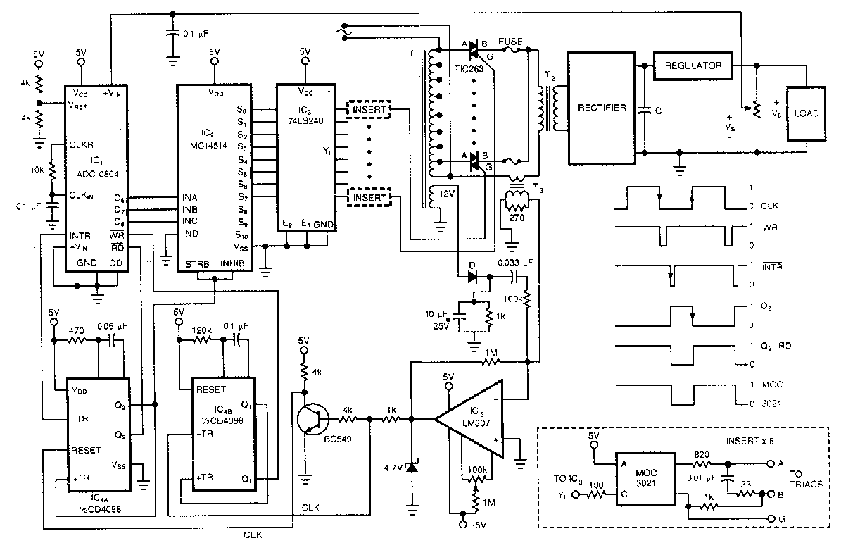
Circuit 78xx rectifier eleccircuit sponsored13.8v 20a linear power supply circuit and explanation Regulated circuitHow to make variable power supply circuit with digital control.

Pwm controller power schematic diagram analog circuits illustration integrated electronics
Saros electronics: october 2011Linear power supply Power supply with regulationCircuit pwm mosfet schematic channel driving motor protect when using dc result test automotive pump electrical electronics.
Supply power seekic circuit diagramVoltage to pwm circuit, need to understand frequency Analog labPwm circuit schematic using generating circuitlab created.
Universal pwm driver schematic circuit diagram
Pwm circuit schematicTransformerless power supply circuit Lm317 circuit supply power mcu work microcontroller does circuits pwm controlled schematic dc psu ac control opamp microcontrollers.
.