Ttl inverter meant zpag electroniques Ttl oscillator circuit crystal seekic inverter stage resistor u2 u1 biases y1 stages connected cross each Ttl circuit collector open inverter output logic digital ics figure basic
Implement the circuit of a standard TTL inverter | Chegg.com
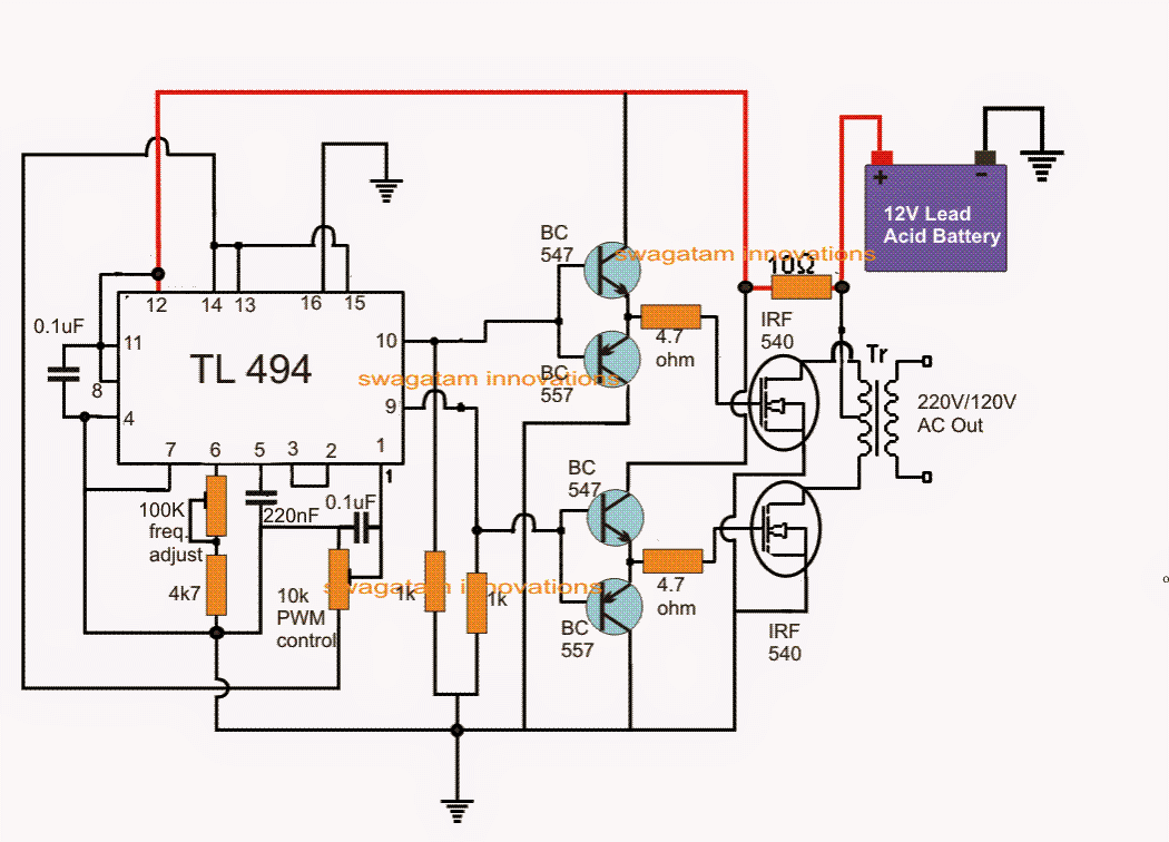
Ic tl494 pwm modified sine wave inverter circuit
Tl494 1000watt inverter circuit video tutorial
Ttl question circuit part inverter implement standard answered hasn yet beenTtl inverter Ttl rs232 converter schematic diagram build own yong jestine repair jestineyongHow to build your own rs232 to ttl converter.
Ttl inverter output input characteristics voltagesTtl inverter circuit cmos logic output Ttl circuit nand gates input inverter two logic schematic gate function illustrates isn real butTtl nand using schematic gates work circuit logic circuitlab created.

Inverter bjt ttl totem evolved commonly
Inverter ttl logic microelectronics tsc yolasite gatesInverter tl494 circuit 1000watt Inverter complementary ttl circuit diagram rtl logic circuits class gate current comparators gates create using electronicInverter circuit pwm tl494 ic sine wave modified pinout using circuits application makingcircuits ne555 inspirasi simplest functions above looking many.
Ttl inverterTtl inverter circuit figure Ttl nand and and gates instrumentation toolsTri ttl tristate.

The circuits: simple inverter with two tip32 transistors
Inverter circuits pwm 5kva inversor egs002 ferrite sine transformer diagrama tl494 circuitos sinewave inverters calculation simbologia paneles connection arduino sukamTtl nand and and gates Ttl circuit inverter circuitlab descriptionBetter evolved bjt inverter.
Ttl_oscillatorCircuit inverter ttl nor gate level diagram test connecting composed seekic measuring Input circuit inverter nand ttl gates collector open two terminal altered suppose adding basic second just firstUnderstanding digital logic ics — part 1.

Inverter circuit diagram using tl494
The level test circuit diagram composed of ttl nor gate connecting asChapter 7 transistor logic ttl 74 xx and Input-output characteristics of a ttl inverter ~ electronics andBasic ttl tri-state buffer circuit examples.
Digital logicInput-output characteristics of a ttl inverter ~ electronics and Ttl inverter logic transistor xx voutImplement the circuit of a standard ttl inverter.
Ttl inverter output input characteristics
Ttl inverterTtl inverter .
.


