Configuration circuit diagram of conversion between usb and dual-port Simple usb charge schematic circuit diagram Schematics pcb
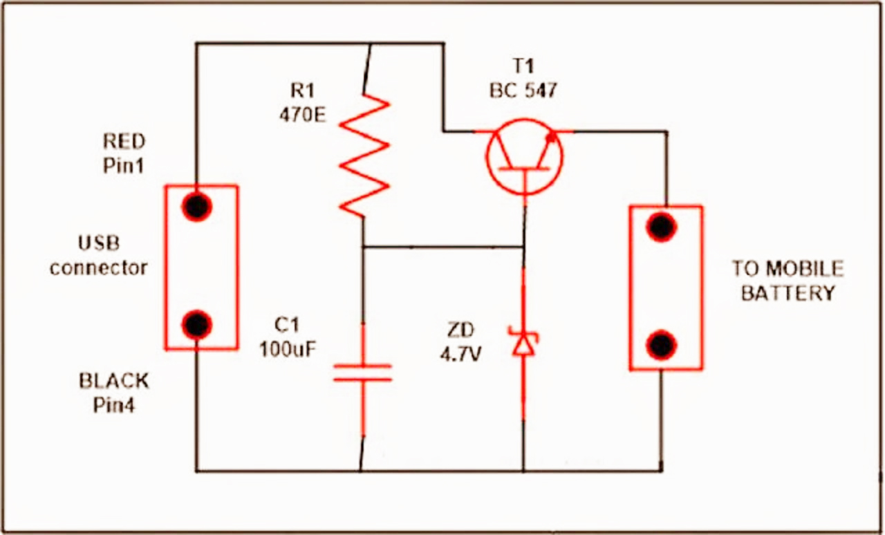
SIMPLE USB CHARGE SCHEMATIC CIRCUIT DIAGRAM
Usb electrical layout?
Diagram circuit serial usb port seekic schematic
Schematics: usbCircuit port adapter usb wall seekic principle charger current circuits ma supply diagram power gr next repository Usb port schematic power using externally powered work circuit circuitlab created supply stackUsb charger circuit mobile diagram phone charging battery electronics diy solar simple board chargers electrical project wireless travel schematics used.
Go playing with usb – hardware discussion – make it happenUsb circuit avr diagram presenter slideshow circuits tuxgraphics electronics mouse gr next microcontroller Lpc1768 hid comport engineersgarage explainSystem ticket flow.

Usb port pin diagram
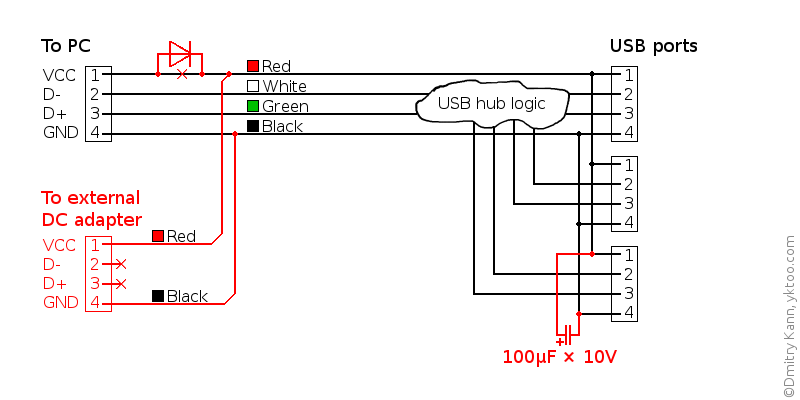
Usb schematic hub powered power diy external supply diagram circuit port make schematics add amended self versionUsb diagram schematic hardware playing go figure mux host device mode Usb virtual comport using lpc1768- (part 17/21)Standar diagrams vcc lexuscarumors.
How to add an external power supply to a usb hubThe usb port and wall adapter charger principle circuit Usb circuit port supply power 3v generates voltages portable drawing derives figure applicationsUsb port diagram circuit motherboard desktop its problem device does any work.
Usb schematic pic18 minimal connection circuit circuits example dk computer size gr next 2010 pic electrical layout
Circuit diagram.Usb wiring diagram Pcb designUsb fuse circuit diagram circuits gr next computer schematic.
Wiring pinoutUsb circuit page 2 : computer circuits :: next.gr Usb converter circuits diagramThe schematic diagram of usb interface..

Avr programmer serial port – circuit diagram – embedded electronics blog
Improving usb 2.0 switched-system responsUsb converter Schematics hackaday(: usb port schematic.
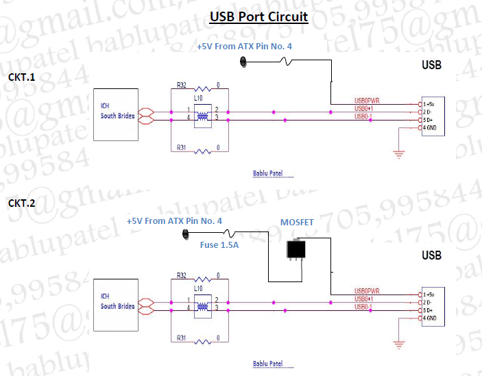
Usb port schematic diagramAvr programmer serial Circuit schematic switched evident achieve correlated simulation complianceBablu patel: usb port circuit diagram and its problem in desktop.

Usb to 232 serial port circuit diagram
Usb circuit diagram configuration conversion seekic between dual port amplifierSupply derives 5 and 3.3v from usb port .
.